Why Tektronix mainframe identification matters before buying
Tektronix produced oscilloscopes across several incompatible plugin families over roughly four decades. A 545B, a 5000-series, and a 7000-series mainframe look similar in eBay photos — large, gray, professional instruments from the same era — but they accept entirely different plugins, have different bandwidth ceilings, and require different calibration fixtures. Buying a mainframe assuming you can use plugins from a different family is an expensive mistake.
The second issue is calibration. A vintage scope "works" if it triggers, sweeps, and displays a waveform. Whether its amplitude and timebase readings are accurate is a separate question, and the answer depends on whether internal trim pots have drifted, whether the CRT high-voltage section is stable, and whether you actually need calibrated accuracy for your intended use. Many bench uses of vintage scopes do not require calibration — troubleshooting logic-level signals, for instance, tolerates significant amplitude error. But RF work and anything requiring voltage measurements to better than 5% does need it.
Tektronix plugin families: compatibility overview
Type plug-in units (500-series, 1950s–1960s)
The earliest Tektronix mainframes — the 535, 545, 545A, 545B, 547, and related models — use "Type" plug-in units designated by letter (Type A, Type B, Type CA, etc.). These plugins are large, vacuum-tube-based or early transistor designs, and they are not compatible with any later Tektronix system. The 545B was produced from approximately 1959 through the mid-1960s and has a 30 MHz bandwidth in its standard vertical configuration.
The 547 added a dual-trace vertical amplifier and extended time-base options. Both the 545B and 547 are capable scopes for audio-frequency and lower-RF work, but their plugin ecosystem is effectively closed — virtually no new plugins were designed after the early 1970s, and sourcing working Type plugins on the secondary market requires patience. Verify that any 545B or 547 listing includes functioning vertical and horizontal plugins before bidding.
5000-series (1960s–1970s)
The 5000 series — mainframes including the 5103N, 5110, and 5403 — use a different, physically smaller plugin format than the Type series. These are solid-state instruments offering bandwidths typically up to 75 MHz or 100 MHz depending on mainframe and plugin combination. The plugin designation system uses numeric codes (5A, 5B prefixes). The 5000 series is generally easier to service than the Type-series tube instruments, but its plugin ecosystem is also largely separate from the 7000 series.
7000-series (1969–1990s): the most practical vintage Tektronix family
The 7000 mainframe system is the most useful Tektronix vintage platform for a working bench, for two reasons: plugin variety and community support. The 7000 series ran from the late 1960s through the 1990s, and the range of available plugins is extraordinarily broad — vertical amplifiers from DC to several hundred MHz, spectrum analyzer plugins, sampling plugins, logic analyzer plugins, and more. Common mainframes include the 7603 (single timebase, 75 MHz), 7613 (storage CRT), 7623A (storage), 7633, 7704A (dual timebase, 250 MHz), and 7834 (400 MHz with storage).
Plugin compatibility within the 7000 family is generally good — most 7-series plugins fit most 7-series mainframes — but there are exceptions. Some high-bandwidth plugins require a mainframe with adequate supply currents; the 7104 (1 GHz) requires the 7104 mainframe specifically. Verify the plugin list against the target mainframe's specifications before assuming compatibility.
| Family | Era | Typical bandwidth | Plugin format |
|---|---|---|---|
| Type (500-series) | 1950s–1960s | 15–30 MHz | Large Type plug-in; tube or early transistor |
| 5000-series | 1960s–1970s | 75–100 MHz | 5-series format; solid-state |
| 7000-series | 1969–1990s | 75 MHz–1 GHz (mainframe-dependent) | 7-series format; widest variety |
CRT phosphor inspection
The cathode ray tube is the component most likely to limit a vintage scope's usability. CRT issues fall into three categories: phosphor burn, geometric distortion, and loss of brightness.
Phosphor burn
Phosphor burn results from prolonged display of a static trace at high intensity — the electron beam continuously exciting the same screen region eventually causes permanent luminescence loss or discoloration at that point. The characteristic signature is a faint greenish or yellowish shadow visible when the CRT is powered but no signal is applied. Moderate burn is cosmetically unpleasant but does not prevent use; severe burn — where the burned region is significantly dimmer than surroundings — degrades measurement accuracy in that display area.
In eBay photos, phosphor burn is visible as a horizontal streak across the center of the CRT at the typical trace position. Request a photo with the scope powered but no input applied (or with the intensity turned down) to see the phosphor condition against a uniform background. A seller who cannot provide this photo is unlikely to have tested the CRT carefully.
Brightness loss
CRT brightness decreases with age regardless of burn — the electron gun cathode depletes over time, and high-voltage regulation in the CRT driver circuit can drift. A scope that "powers on and displays a trace" may have a trace barely visible at maximum intensity. Brightness loss is less repairable than most other scope faults — CRT replacement or regen (cathode rejuvenation) are the options, both requiring skill and specialist equipment.
Geometric distortion
If the CRT's deflection plates or high-voltage focus circuits have drifted, the displayed trace will be non-linear — sweeps that curve, grids that don't align, or traces that shift with brightness changes. This is typically a calibration and component fault, not a CRT fault, and is more often repairable.
What calibration involves for a vintage scope
Calibration of a vintage oscilloscope involves verifying and adjusting the instrument against a traceable reference standard. For a typical 7000-series scope, this means checking vertical amplifier gain accuracy across the V/div range, timebase accuracy across the time/div range, trigger sensitivity and triggering point accuracy, and (for storage scopes) the storage write speed calibration.
The calibration fixtures for Tektronix scopes are themselves specialized instruments. Tektronix produced calibration fixtures including the SG 502, SG 504, and various oscilloscope calibrators designed for specific mainframe families. Generic signal generators and frequency counters can substitute for many calibration steps, but verifying rise-time specifications at the upper bandwidth limit requires a signal source with a fast enough rise time — which for a 250 MHz scope means a source with a rise time under roughly 1.4 ns, which is not a typical bench signal generator.
Practically: if you are using a vintage scope as a general-purpose bench tool for audio, lower-frequency digital work, or qualitative RF troubleshooting, calibration is not a prerequisite for useful work. If you need traceable amplitude accuracy — for production test, compliance measurement, or RF power measurement — a vintage scope needs calibration and you should factor that cost into the acquisition price. NIST-traceable calibration for a vintage scope at an independent cal lab typically costs more than many vintage scopes are worth, which is why most working-bench users do not pursue it.
HP 8640B signal generator: buying guide
The HP 8640B is a 500 kHz to 512 MHz RF signal generator with AM and FM modulation, internal modulation sources, and a mechanical precision analog readout. It was produced from the early 1970s through the 1980s and remains a capable RF signal source for receiver alignment, sensitivity testing, and antenna work.
The 8640B's key wear points are the mechanical tuning mechanism and the output attenuator. The main tuning uses a precision gear-driven mechanism that can develop backlash with age; significant backlash makes setting a precise frequency difficult. The output level attenuator uses a rotary switch with multiple contact sets — worn or dirty contacts cause output level jumps at switch positions. Both issues are repairable but require disassembly.
Frequency accuracy on a stored 8640B will have drifted from its original specification. The internal crystal timebase can be adjusted; verify the output frequency against a known reference (GPS-disciplined frequency standard or calibrated counter) before relying on the front-panel readout for anything frequency-critical. Output level accuracy is a separate calibration point — the level display is accurate only if the attenuator contacts are clean and the RF output section has been verified.
Fluke 8060A multimeter: identification and assessment
The Fluke 8060A (introduced approximately 1981) was Fluke's flagship handheld true-RMS multimeter for its era. It measures AC and DC voltage to 1000V, resistance, frequency (to 200 kHz), and includes a continuity buzzer and diode test. The true-RMS AC voltage measurement is its defining capability relative to average-responding meters of the same period.
Common failure modes on 8060A units include dead or partially dead LCD segments (the LCD bonds to its driver IC age and fail), input protection fuse failure (the input fuses are board-mounted and non-obvious to replace), and battery contact corrosion from years of storage with batteries installed. Verify all digits display in all modes, test the resistance ranges (these use a separate front-end and fail independently of the voltage ranges), and check the AC frequency function if that capability matters to your use case.
Calibration on the 8060A is performed via internal trim pots accessible through the rear of the instrument. The DC voltage ranges are typically stable over decades of storage; the AC RMS circuitry can drift more. A working 8060A without calibration documentation is useful for most bench purposes; if you need DC accuracy better than 0.5%, verify against a known reference.
eBay buying checklist for vintage test equipment
- For any Tektronix scope: confirm which plugin family (Type / 5-series / 7-series) and verify plugins are included in the listing
- Request a powered-on photo with a signal applied — "powers on" without a trace is not a working scope
- Ask for a photo with the intensity set low showing the CRT background — phosphor burn is visible this way
- For 7000-series mainframes: confirm which specific mainframe model and which plugins are included; bandwidth and capability depend entirely on the combination
- For HP 8640B: ask whether the tuning mechanism has backlash and whether the output level has been checked against a reference
- For Fluke 8060A: verify all LCD segments in all modes, check battery compartment for corrosion
- Shipping vintage test equipment: heavy, fragile CRTs need professional packing; avoid listings offering "buyer arranges courier" without inspection of the packing
- Factor in calibration cost separately if traceable accuracy matters for your application
Search eBay for vintage test equipment
 Tektronix 545B oscilloscope
Verify Type plug-in units are included; the mainframe alone is worth very little.
Tektronix 545B oscilloscope
Verify Type plug-in units are included; the mainframe alone is worth very little.
 Tektronix 7000-series scope
Most practical vintage Tek family — check mainframe model and plugin inventory carefully.
Tektronix 7000-series scope
Most practical vintage Tek family — check mainframe model and plugin inventory carefully.
 HP 8640B signal generator
Ask about tuning backlash and output level accuracy before bidding.
HP 8640B signal generator
Ask about tuning backlash and output level accuracy before bidding.
 Fluke 8060A multimeter
Verify all LCD segments; check battery compartment for corrosion from storage.
Fluke 8060A multimeter
Verify all LCD segments; check battery compartment for corrosion from storage.
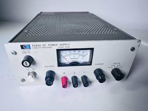 Vintage HP test gear
Service manuals often still available from Keysight archive — a major sourcing advantage.
Vintage HP test gear
Service manuals often still available from Keysight archive — a major sourcing advantage.