Why vintage ham gear still makes sense
The practical case for vintage HF gear is straightforward: the engineering that went into 1960s–1980s amateur transceivers and receivers was serious. Collins, Drake, Kenwood, and Yaesu built equipment to a durability standard that modern budget gear rarely matches. A well-maintained Drake R-4C can still outperform budget SDRs in adjacent-channel rejection. A Yaesu FT-101 on 40 meters will work the world.
The cost of ownership is different from modern gear: parts sourcing is the challenge, not the electronics. Most vintage ham gear fails in predictable places — electrolytics, final tubes, alignment drift — and those failures are fixable with patience and a soldering iron. What follows is a platform-by-platform breakdown of what each set needs.
Yaesu FT-101 series: variants and tube complement
The FT-101 series spans several years and multiple variants with important differences in final tube type and band coverage. The original FT-101 covers 160–10m (minus the WARC bands, which didn't exist yet) and uses a 12BY7A driver with a pair of 6JS6C finals. This tube combination was chosen for availability and reasonable cost; both types remain producible and are currently available from new-old-stock and reproduction sources, though at higher prices than historical.
| Variant | Final tubes | Notable differences |
|---|---|---|
| FT-101 | 12BY7A + 6JS6C pair | Base model, 160–10m, no WARC |
| FT-101E | 12BY7A + 6JS6C pair | Improved VFO stability, revised ALC |
| FT-101EE | 12BY7A + 6KD6 pair | Higher-power final option; 6KD6 harder to source |
| FT-101F | 12BY7A + 6JS6C pair | Added 17m/12m coverage in some versions |
| FT-101ZD | 12BY7A + 6JS6C pair | Late model; solid-state finals available as retrofit |
Common FT-101 failure points
The electrolytic capacitors in the power supply section age and fail, causing hum on transmit and erratic bias behavior. Replacing these before use is standard practice on acquired units. The VFO section uses a temperature-compensated capacitor stack that drifts with age — a 30-minute warmup before operating is normal. If frequency drift continues beyond 15–20 minutes of warmup, the VFO capacitors likely need attention.
The PA (power amplifier) bias adjustment is a critical maintenance procedure. Over-bias runs the final tubes hot and shortens their life; under-bias produces distorted audio. The procedure requires a dummy load, wattmeter, and multimeter — not complex, but worth doing correctly rather than leaving to guesswork.
Kenwood TS-820S: hybrid design and what fails
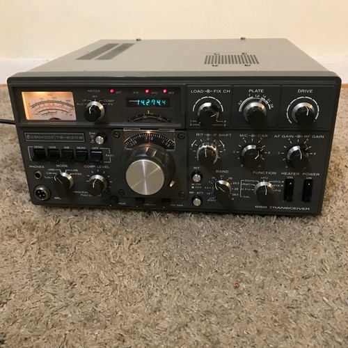
The TS-820S represents the transitional era of 1970s amateur HF design: solid-state receiver and driver stages combined with a tube PA. The final amplifier uses 6146B tubes, which are a standard type also used in many commercial broadcast transmitters — meaning supply is better than for the more specialized Yaesu tube types. The 6146B operates at plate voltages around 600–700V; this is dangerous but manageable with proper procedure.
TS-820S failure profile
The main electrolytic capacitors in the high-voltage power supply section are the most common failure point. These age at room temperature regardless of use. A unit that hasn't been powered in 10+ years should have its electrolytics inspected before use, particularly in the B+ supply. Second common failure: the ALC (automatic level control) circuit uses age-sensitive components that cause over-driven transmit audio — a symptom that experienced operators recognize as characteristic of this model family.
The receiver front-end is solid-state and generally reliable. Pre-amp transistors are the most likely receiver failure; they are standard types that can be matched and replaced. The VBT (variable bandwidth tuning) filter is a clever implementation that works well when properly aligned — alignment drift is common and restorable.
Drake R-4C: the golden-era receiver
Drake's R-4C (and its companion T-4XC transmitter) represents the peak of 1970s amateur HF receiver design. The R-4C is a triple-conversion receiver with a 9 MHz first IF. Its key performance driver is the selectivity filter in the second IF — Drake offered optional mechanical filters (manufactured by Collins) that provide extremely narrow selectivity for CW and SSB work. A stock R-4C without these optional filters is a capable receiver; an R-4C with a full set of Collins filters is a reference-class instrument.
IF filter identification
The optional filters install in labeled slots on the front panel — the presence of filters is visible from the front without opening the unit. Filter bandwidths were offered in several options: typically 500 Hz (CW), 1.8 kHz (narrow SSB), and 3.3 kHz (wide SSB). A unit advertised with "all filters" should have filters physically present in all filter positions; verify from photos before buying.
Alignment on the R-4C
The R-4C alignment is complex and requires appropriate test equipment: a calibrated signal generator, a frequency counter, and an oscilloscope. The triple-conversion design means three IF stages each need alignment. This is not a beginner procedure. Most working R-4C units found today are somewhat out of alignment; a fully aligned unit commands a meaningful premium and is worth the premium if you don't have the equipment to do it yourself.
Hallicrafters SX-101: 1950s all-tube design
The Hallicrafters SX-101 (introduced approximately 1957) is an all-tube HF receiver covering 80–10m. The tube complement is approximately 18 tubes, including several dual-purpose types. The SX-101A is a minor revision of the SX-101 with small circuit improvements.
This receiver was designed to meet the performance expectations of serious amateur operators in the late 1950s. By modern standards it has limited adjacent-channel rejection compared to the Drake R-4C, but its audio quality is warm and pleasant for AM and SSB copy on a quiet band. The build quality is typical of 1950s American instrument construction — heavy, well-ventilated, and repairable with standard tube types.
Tube replacement on the SX-101
The most critical tubes to test and replace on any SX-101 acquisition: the IF amplifier tubes (typically 6BA6 or similar), which directly affect receiver sensitivity; and the detector/product detector stage tubes, which affect audio quality. All SX-101 tube types are standard receiving tubes that remain available. A full re-tube with tested tubes and a 30-minute warmup alignment check will revive most units found in good cosmetic condition.
Tube replacement and matched pairs
For tube final amplifiers, tube replacement is not simply "put in new tubes." The final tubes should be biased correctly after replacement, and for push-pull designs (like the FT-101 pair), the tubes should be reasonably matched for transconductance. Matched pairs are sold as such by major tube suppliers — a matched pair costs somewhat more than individual tubes but produces more symmetric output and longer tube life than unmatched pairs.
Where to source tubes currently: established tube suppliers (Antique Radio Supply, Tube Depot, the major European suppliers) carry current-production equivalents for most common amateur types. For the 6JS6C specifically, current production tubes from Eastern European manufacturers are available but vary in quality; prioritize tested and graded tubes for PA service. Verify current availability and pricing before purchase as tube markets fluctuate.
ATU pairing for vintage gear
Vintage HF transceivers typically expect to drive a 50-ohm load. Most were designed for wire antennas through a tuner — antenna tuning units (ATUs) were standard accessories. For an FT-101 or TS-820S driving a multiband wire antenna, a manual L-network or T-network ATU is appropriate. Avoid high-SWR loads at the transceiver output; tube finals tolerate moderate mismatch but not sustained high-SWR operation.
External ATUs compatible with vintage gear: classic manual tuners like the MFJ-969, Johnson Matchbox (for all-vintage shacks), or Dentron units match the era and work correctly. The key specification is power handling — for a 100W HF transceiver, a 300W-rated tuner provides adequate headroom. Modern auto-tuners work correctly with vintage transceivers but look incongruous.
eBay buying checklist for vintage ham gear
- Ask for the specific model variant — FT-101 vs FT-101E vs FT-101EE differ meaningfully
- Confirm whether the unit transmits — receive-only units are worth significantly less
- Ask about final tube brand and condition — original tubes are a plus if tested
- For the Drake R-4C: request photos of the filter position panel showing installed filters
- Ask whether the unit has been recently serviced or has known issues
- For any tube gear: confirm the power supply section has been inspected (capacitors)
- Confirm power output on transmit — a stated "100W output" is verifiable with a wattmeter test the seller can describe
Search eBay for vintage ham gear
 Yaesu FT-101
Confirm the variant suffix (E, EE, F, ZD) — tube types differ between variants.
Yaesu FT-101
Confirm the variant suffix (E, EE, F, ZD) — tube types differ between variants.
 Kenwood TS-820S
6146B finals are standard and available. Ask about electrolytic cap condition.
Kenwood TS-820S
6146B finals are standard and available. Ask about electrolytic cap condition.
 Drake R-4C
Confirm IF filter presence. Filters add significant value — verify from photos.
Drake R-4C
Confirm IF filter presence. Filters add significant value — verify from photos.
 Hallicrafters SX-101A
18-tube complement — all standard types, still available. Budget for a full re-tube.
Hallicrafters SX-101A
18-tube complement — all standard types, still available. Budget for a full re-tube.
 Collins KWM-2
Premium pricing reflects premium engineering. Dedicated restoration community with service documentation.
Collins KWM-2
Premium pricing reflects premium engineering. Dedicated restoration community with service documentation.