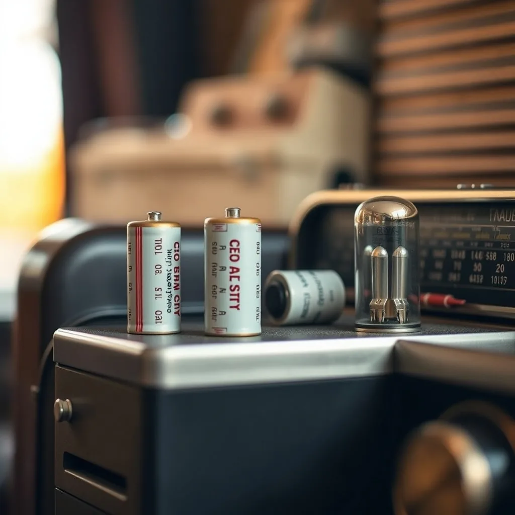
High voltage hazard
Tube radios operate at plate voltages of 150–400 volts DC. The main filter capacitors retain this charge after power-off and can deliver a dangerous shock. Always discharge the filter capacitors before working inside a tube radio chassis. The procedure is described in the section on electrolytics below. Do not skip it.
Recapping a tube radio — replacing aged capacitors before or after failure — is one of the most common restoration tasks in vintage radio work. Capacitors are the component most likely to fail with age, and failed capacitors in a tube radio cause a range of problems: distorted or absent audio, hum on the output, intermittent operation, and in the worst cases, fire. A radio that is "working but sounds off" almost always has capacitor-related problems.
The task is approachable for someone with basic soldering skills and a logical approach to the sequence. The challenge is that tube radio chassis contain four distinct types of capacitors — wax-paper, electrolytic, mica, and ceramic (or molded film in later sets) — and they require different handling, have different failure rates, and are not all candidates for routine replacement. Understanding the differences before you start prevents wasted time and money on parts that don't need replacing.
The Four Capacitor Types and Their Failure Modes
Wax-paper capacitors
Wax-paper capacitors are the most common capacitor in radios from the 1930s through the mid-1950s. They are cylindrical, usually 0.5 to 2 cm in diameter, with two axial leads, and covered in a paper-and-wax coating that is often brown, tan, or dark red. Many are marked with color-code bands similar to resistors; others have printed values.
The construction is layers of paper soaked in wax, interleaved with foil conductors. The problem is that the wax dries and cracks with age, the paper absorbs moisture, and the result is a capacitor with dramatically increased leakage current — the capacitor passes DC current where it should block it. In a tube radio, a leaky wax-paper capacitor in a coupling position passes plate voltage into a grid, biasing the tube incorrectly. The practical effects are distortion, reduced output, and in some cases tube damage.
The standard practice is to replace all wax-paper capacitors in a set you are restoring, regardless of whether they test within tolerance. Leakage is not always measurable with a standard capacitance meter; you need a dedicated capacitor leakage tester to catch bad actors, and even passing capacitors of this age are on borrowed time. The cost of the parts is low — most wax-paper caps are replaced with modern film capacitors of equivalent value at a cost of ten to fifty cents each — and the labor cost of returning later to chase audio problems caused by a leaky cap you left in is high.
What to replace them with
Modern polyester film capacitors (often called Mylar capacitors) are the standard replacement for wax-paper caps. Match the capacitance value (in microfarads or picofarads as marked) and use a voltage rating equal to or higher than the original. For most coupling and bypass capacitors in consumer radios, a 400V or 630V film capacitor is appropriate even if the original was rated 200V — higher voltage ratings in modern small film caps cost negligibly more and provide safety margin.
The physical size of modern film capacitors is typically smaller than the original wax-paper cap. For a chassis where original appearance matters, tubular film caps in similar dimensions exist, but for functional restoration, standard axial film caps work perfectly.
Electrolytic capacitors
Electrolytic capacitors are the large, cylindrical components — typically 1 to 4 cm in diameter and 2 to 5 cm tall — used as filter capacitors in the power supply section. Their job is to smooth the rectified AC line voltage into stable DC. They are polarized (the positive and negative terminals must be connected correctly) and they operate at the highest voltages in the set — often 300 to 400 volts DC.
Electrolytic capacitors fail differently from wax-paper caps. They dry out over decades — the liquid electrolyte inside evaporates slowly through the seals. A dried-out electrolytic has greatly reduced capacitance and increased equivalent series resistance (ESR), which means it no longer smooths the power supply effectively. The result is 60 or 120 Hz hum in the audio output that persists regardless of volume setting. Some dried-out electrolytics also leak or vent, leaving a brown or white residue around the base.
Replace the main filter electrolytics. These are always suspect in a set that hasn't been serviced and are the first thing to check when hum is the presenting symptom.
Discharge before working
The main filter capacitors store charge at plate voltage — 300–400V in typical sets — and retain this charge after power is removed. To discharge: unplug the radio, wait 30 seconds, then connect a 10k–25k ohm resistor (2 watt or higher) across each electrolytic cap's terminals for 30 seconds per cap. Do not use a direct short — the resistor limits current and prevents a spark that could damage the cap lead connections. After discharging, verify with a voltmeter that voltage is below 10V before touching any connections.
Reforming old electrolytics
If a set is rare or the electrolytics are an unusual value that is difficult to source as modern replacements, there is an alternative to immediate replacement called reforming. This involves applying a gradually increasing DC voltage to the capacitor — starting below its rated voltage and slowly raising it over 20 to 30 minutes — which re-forms the aluminum oxide dielectric layer that the capacitor relies on. A variac (variable autotransformer) and a current-limiting resistor in series with the cap are the standard setup.
Reforming works on electrolytics that are dried out but not physically damaged. It is not a substitute for replacement in a set you intend to use regularly — a reformed electrolytic will likely fail again within a few years — but it can bring a valuable set to life long enough to evaluate it before committing to a full recap.
Mica capacitors
Mica capacitors are small, flat, rectangular components — often silver or pink, sometimes molded into a rectangular block — used in RF and IF (intermediate frequency) circuits where precise, stable capacitance values are critical. They are found in tuned circuits and IF transformers.
Mica capacitors are the most stable capacitors in vintage radio construction. The mica dielectric does not absorb moisture, does not crack with age, and does not dry out. A mica capacitor from 1940 typically still measures within a few percent of its marked value and has negligible leakage.
Do not replace mica capacitors as part of a routine recap. They rarely fail, and if they test within tolerance on a capacitance meter, there is no functional reason to replace them. The only scenario where replacing mica caps makes sense is if a specific one tests significantly out of tolerance or shows visible physical damage.
The exception is silver mica capacitors from certain manufacturing periods that are affected by "silver migration" — a phenomenon where silver ions migrate through the mica and create leakage paths. These show up as anomalous behavior in high-frequency circuits. If you have unexplained problems in the RF or IF section after replacing all the wax-paper caps, a silver mica cap with silver migration is worth considering, but it is not a routine recap item.
Ceramic and film capacitors
Post-1950s radios increasingly used ceramic disc capacitors and later, molded plastic film capacitors in positions that earlier sets used wax-paper caps. These components age better than wax-paper construction — ceramic caps are stable and rarely fail, and molded film caps are substantially more durable than wax-paper.
In a set from the late 1950s or 1960s, inspect ceramic caps visually and test any that are in critical signal paths if you have a capacitance meter with leakage testing. Replace any that are cracked or visually damaged. As a class, they are not routine recap candidates the way wax-paper caps are.
The Order to Recap
The sequence of a recap matters for safety and for systematic troubleshooting. A rational order:
1. Document before you unsolder anything
Photograph the chassis from multiple angles before touching it. Note the value, voltage rating, and physical orientation (for polarized electrolytics) of every capacitor you will replace. Write down or photograph the schematic reference number if the chassis has markings. A mistake in the capacitance value or polarity of a filter cap can cause immediate damage when you power up.
2. Discharge and handle the main filter electrolytics first
Discharge the main filter caps as described above before doing any other work inside the chassis. This makes the rest of the job safe to do without repeatedly checking voltages. Replace the main filter electrolytics before powering up for any testing — a shorted or severely degraded main filter cap can take out other components when the set is powered.
3. Replace all wax-paper capacitors
Work through the chassis systematically, replacing every wax-paper cap one at a time. Replace each cap before moving to the next — do not remove multiple caps simultaneously, as this creates confusion about original values and connections. As you go, check that replacement caps have the correct value (within 10–20% tolerance is normal; coupling caps are not precision components) and adequate voltage rating.
In the audio output stage, pay particular attention to coupling capacitors between stages and the cathode bypass capacitors. These are in positions where a leaky cap has the most audible effect. Tone control capacitors can shift audio character if they change value, but they are not safety-critical.
4. Replace secondary electrolytics in the audio section
Many sets have smaller electrolytic capacitors in the audio section — cathode bypass caps, tone circuit electrolytics — in addition to the main power supply filter caps. Replace these after the main filter caps are done. These smaller values are typically 1–50 µF at lower voltages (25–100V) and are readily available as modern equivalents.
5. Test and evaluate mica caps last
After the wax-paper and electrolytic replacement is complete and the set powers up, evaluate the RF and IF performance. If sensitivity, selectivity, or station separation is poor after the other caps are replaced, then investigate the mica caps in the IF transformers and RF tuned circuits. Replace only those that test out of tolerance or are associated with a specific failure. Replacing all mica caps speculatively adds cost and risk of misidentification without meaningful benefit.
Common Mistakes and How to Avoid Them
- Getting the polarity wrong on an electrolytic. An electrolytic installed backwards will pass current instead of blocking it and will likely fail catastrophically — venting, leaking, or in older chassis with slow fuses, burning. Always verify polarity from your pre-work documentation and against the schematic before powering up.
- Using too-low a voltage rating. Matching capacitance value is mandatory; matching voltage rating is the minimum. Using a 50V cap in a position rated for 200V in the original circuit is a failure waiting to happen. Always match or exceed the original voltage rating.
- Leaving a wax-paper cap because it "looks fine." A wax-paper cap that passes a standard capacitance test can still have leakage that the test doesn't catch. The standard advice exists for a reason: replace them all.
- Replacing mica caps speculatively. The opposite error — swapping mica caps "while you're in there" — can introduce new problems if you accidentally misread a value or damage a circuit trace. Mica caps should be replaced with cause, not as routine.
- Working live. Any component check or adjustment on a live chassis should be done only when necessary and with a single insulated probe, keeping one hand behind your back. Plate voltages in tube radios are above the threshold for cardiac arrest.
After Recapping: First Power-Up
The first power-up after a recap should be done with current limiting — either through a dim bulb tester (a 60–100W incandescent bulb in series with the AC line) or a variac with current metering. A dim bulb tester provides immediate visual feedback: if the bulb lights brightly and stays bright, something is drawing excessive current. If it briefly lights and dims to a glow as the tubes warm up, the set is behaving normally.
Listen and smell during the first power-up. A burning smell, smoke, or a bulb that stays brightly lit are all reasons to cut power immediately and investigate before continuing. Most properly recapped sets come up cleanly on the first power-up and the improvement in audio quality — removal of hum, restoration of clear audio — is often immediately obvious.
Gear for tube radio recapping
Smart eBay searches for the tools and supplies in this guide. We earn a small commission on qualifying sales; the price you pay is the same either way. Full disclosure.
 Film capacitor assortment kit
Axial polyester film capacitor assortment kits cover most values needed for wax-paper replacement. Look for 400V or 630V rated kits — the higher voltage rating is worth the minor premium.
Film capacitor assortment kit
Axial polyester film capacitor assortment kits cover most values needed for wax-paper replacement. Look for 400V or 630V rated kits — the higher voltage rating is worth the minor premium.
 Electrolytic capacitors (high voltage)
Main filter caps typically need 350–450V rated electrolytics. Match or exceed original rating. Physically larger modern caps may require chassis mounting bracket adaptation.
Electrolytic capacitors (high voltage)
Main filter caps typically need 350–450V rated electrolytics. Match or exceed original rating. Physically larger modern caps may require chassis mounting bracket adaptation.
 Capacitor ESR / leakage tester
A standard capacitance meter misses the leakage current that kills tube radio performance. An ESR or dedicated capacitor leakage tester finds what a basic meter doesn't.
Capacitor ESR / leakage tester
A standard capacitance meter misses the leakage current that kills tube radio performance. An ESR or dedicated capacitor leakage tester finds what a basic meter doesn't.
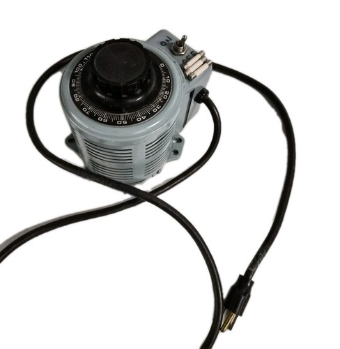 Variac (variable autotransformer)
Used for reforming old electrolytics and for controlled first power-up after restoration. Vintage Powerstats and Superior Electric models hold up well; buy by rated current for your needs.
Variac (variable autotransformer)
Used for reforming old electrolytics and for controlled first power-up after restoration. Vintage Powerstats and Superior Electric models hold up well; buy by rated current for your needs.
 Temperature-controlled soldering station
Vintage radio work uses tag strip and terminal board connections that tolerate heat differently from PC board pads. A temperature-controlled station prevents overheating old connection points.
Temperature-controlled soldering station
Vintage radio work uses tag strip and terminal board connections that tolerate heat differently from PC board pads. A temperature-controlled station prevents overheating old connection points.